Series 110…41-605
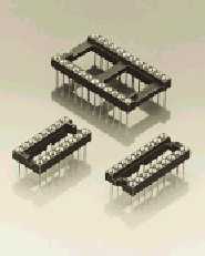
Dual-in-line sockets automatic insertion
Open frame
Solder tail
Thanks to the new design
of the insulator body, this
socket line is fully com-
patible with all standard
automatic insertion
equipment
– Chamfered contact
entries for easy IC inser-
tion without bent leads.
– Soft copper alloy ma-
chined contact allows
clinching
Insertion characteristics:
4-finger standard
Platings
Sleeve
Clip
Pin
91
5 mm Sn Pb
0.25 mm Au
93
5 mm Sn Pb
0.75 mm Au
97
5 mm Sn Pb
Goldflash
99
5 mm Sn Pb
5 mm Sn Pb
Ordering information
For standard versions see table (order codes)
Option:
For multilayer boards up to 3.4 mm, solder tail 4.2 mm, we offer
series 111-xx-xxx-41-613
6
110-91-306-41-605
110-93-306-41-605
110-97-306-41-605
110-99-306-41-605
Fig. 100
7.6
7.62
10.1
8
110-91-308-41-605
110-93-308-41-605
110-97-308-41-605
110-99-308-41-605
Fig. 101
10.1
7.62
10.1
14
110-91-314-41-605
110-93-314-41-605
110-97-314-41-605
110-99-314-41-605
Fig. 102
17.7
7.62
10.1
16
110-91-316-41-605
110-93-316-41-605
110-97-316-41-605
110-99-316-41-605
Fig. 103
20.3
7.62
10.1
18
110-91-318-41-605
110-93-318-41-605
110-97-318-41-605
110-99-318-41-605
Fig. 104
22.8
7.62
10.1
20
110-91-320-41-605
110-93-320-41-605
110-97-320-41-605
110-99-320-41-605
Fig. 105
25.3
7.62
10.1
24
110-91-324-41-605
110-93-324-41-605
110-97-324-41-605
110-99-324-41-605
Fig. 106
30.4
7.62
10.1
22
110-91-422-41-605
110-93-422-41-605
110-97-422-41-605
110-99-422-41-605
Fig. 107
27.8
10.16
12.6
24
110-91-624-41-605
110-93-624-41-605
110-97-624-41-605
110-99-624-41-605
Fig. 17
30.4
15.24
17.7
28
110-91-628-41-605
110-93-628-41-605
110-97-628-41-605
110-99-628-41-605
Fig. 18
35.5
15.24
17.7
32
110-91-632-41-605
110-93-632-41-605
110-97-632-41-605
110-99-632-41-605
Fig. 19
40.6
15.24
17.7
40
110-91-640-41-605
110-93-640-41-605
110-97-640-41-605
110-99-640-41-605
Fig. 108
50.6
15.24
17.7
No.
Insulator
of
Order Codes
dimen-
poles
sions
Plating 91
Plating 93
Plating 97
Plating 99
See
A
B
C
page 52